These photos were taken in June 2001
Updated: February 15, 2006
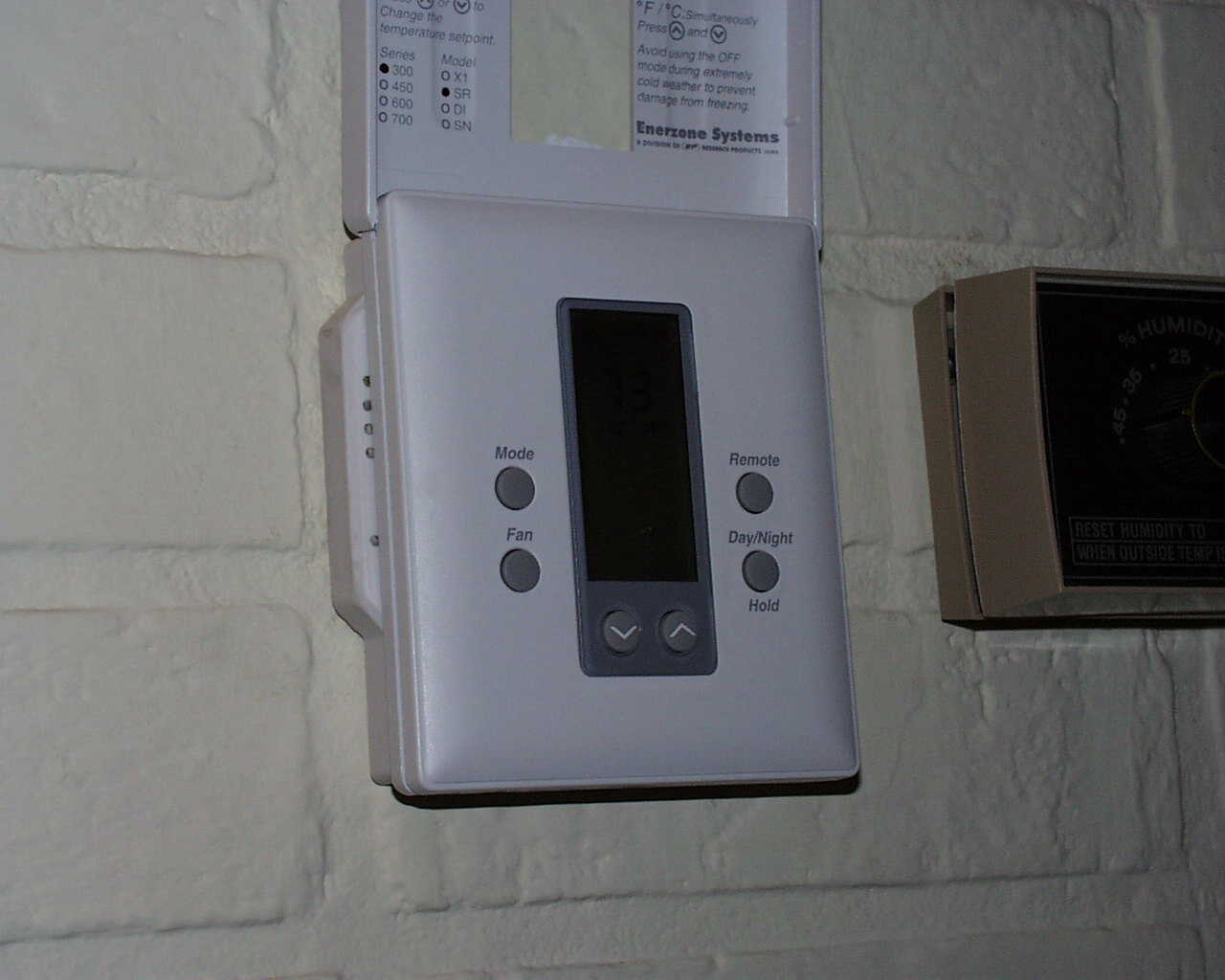
Pictured above is the Slimline Dry Contact Thermostat with a digital communication module. The module is sandwiched between the thermostat and the wall, and not only includes high speed communications, but also has four discrete contact inputs and four digital outputs capable of driving 5 VDC relays. The thermostat provides four groups of setpoints that can be controlled via the communication link or contact closure. The box shown center right is the humidifier sensor/controller.
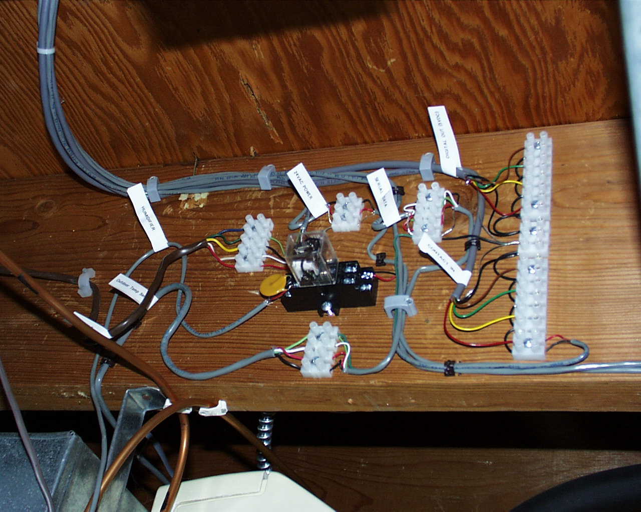
Pictured above is the cable connections breakout area located between the rafters in the basement. Upper left shows the cable assembly coming from the thermostat/com module and breaking out to various connectors. In the center shows a 24 VAC relay driven by the humidifier sensor and whose contacts are wired to one of the discrete contact inputs of the thermostat. There are six cables running up to the thermostat.
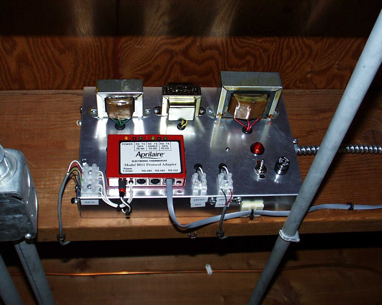
Shown above is the power supply module. Three transformers provide power to the thermostat, the protocol communications adapter (red box shown center left), and home security sensors. The module is fused and switched separately from the furnace and air conditioning power.
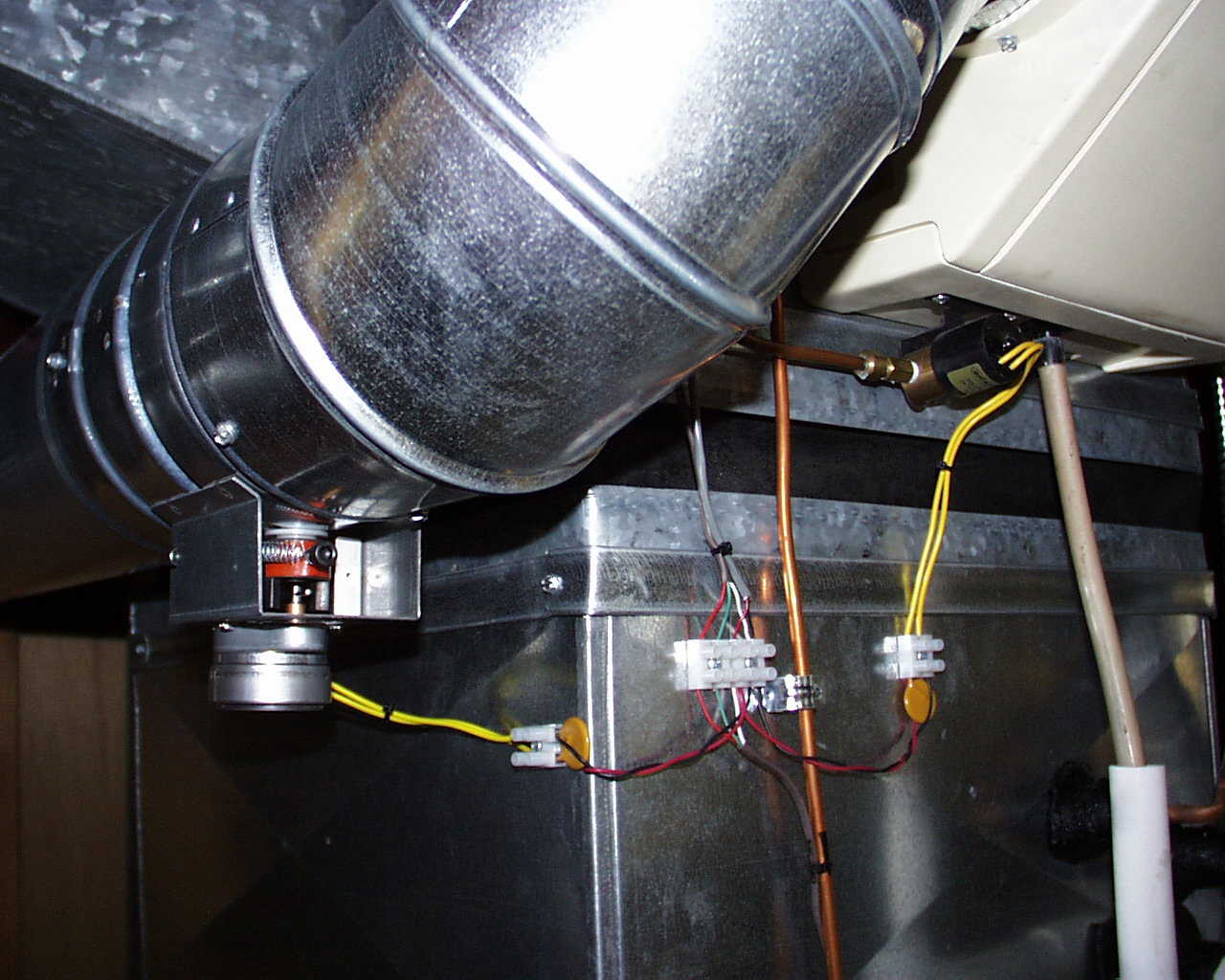
Shown center left is the motorized duct damper and the humidifier electric water valve shown upper right. If the furnace is running and the humidity is below the setpoint, the duct damper is opened and the water valve is operated.
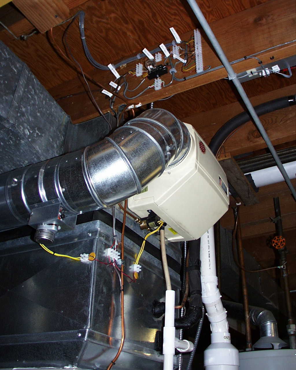
Pictured above shows the humidifier, the cable breakout area, and the lower portion of the power supply module.
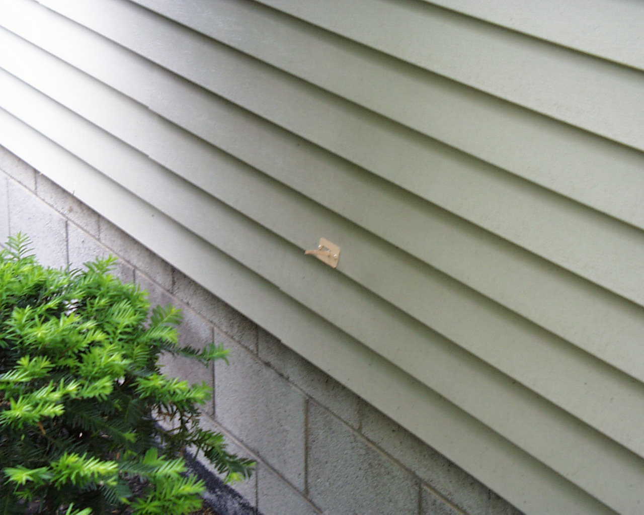
Shown above is the remote outdoor temperature sensor. The sensor is mounted on the shadow side of the house.
Pictured above shows direct PC access with the thermostat using HyperTerminal. A unique ASCII text file profile shown left is created, then downloaded to the thermostat by HyperTerminal. When a change-of-state (cos) occurs within the thermostat, a message is sent and displayed as shown above. "T=" indicates the new indoor temperature, "R=" indicates the new outdoor temperature, while "HVAC=" indicates a cos occurring within the thermostat which in turn operates the furnace or air conditioner. The profile shown left selects the auto mode, "m=auto", which will operate the air conditioner when the indoor temperature rises above setpoint cool, "sc=75", or operate the furnace when the temperature falls below setpoint heat, "sh=73".
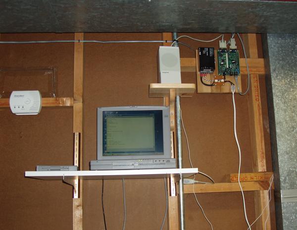
Pictured above right is the 80C400 Web Server Kit. The thermostat's RS232 port is connected to this server.
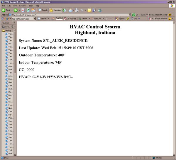
Pictured above is the webpage being served by the 80C400 controller. The firmware was developed using the Java programming language.
Many of the parts shown above were purchased from http://www.smarthome.com
![]()