![]()
Multi-Spark Gap Experiments
UPDATED: February 23, 2006
Excess electrical energy has been discovered in multi-spark gaps using Carbon/Graphite - Thoriated Tungsten rods with a Coefficient of Performance (COP) greater than 100% across the gap. A Wimshurst Generator is used as a primary high-voltage dynamo. A Tesla-like step-down transformer T1 with a ferrite rod is used to efficiently reduce the high-voltage down to safe practical levels, which can easily be distributed and measured. As shown in Fig. 1, successive electric discharges or Electrum Validum (EVs) discharges are generated, and their associated energy is collected in a 10uf low loss capacitor during a given period of time. An array of up to three spark gaps wired in series have been tested.
The energy stored in a capacitor is calculated as follows:
E = ½ C V²
Where,
E is the energy stored in the capacitor.
C is the capacitance.
V is the voltage across the capacitor.
The Wimshurst Generator used in this experiment is capable of generating voltages up to 75,000 volts, and is available from Edmund Scientific.
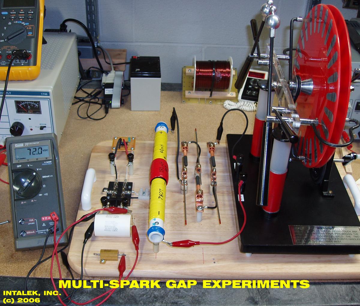
Figure 1. Multi-spark gap experiments using the Wimshurst Generator.
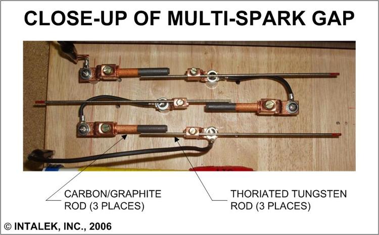
Figure 2. Close-up view of three Carbon/Graphite - Thoriated Tungsten spark gaps wired in series.
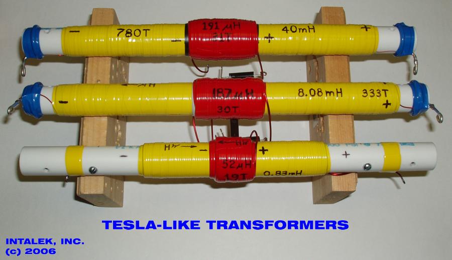
Figure 3. A variety of single layered Tesla-like transformers are tested.
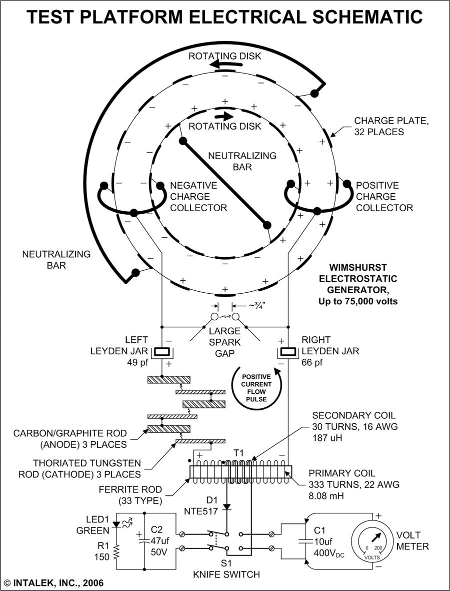
Figure 4. Wimshurst Generator test platform electrical schematic using 333 turn primary.

Figure 5. Test results using 333 turn primary and three spark gaps.

Figure 6. The COP calculation for 333 turn primary and three spark gaps.
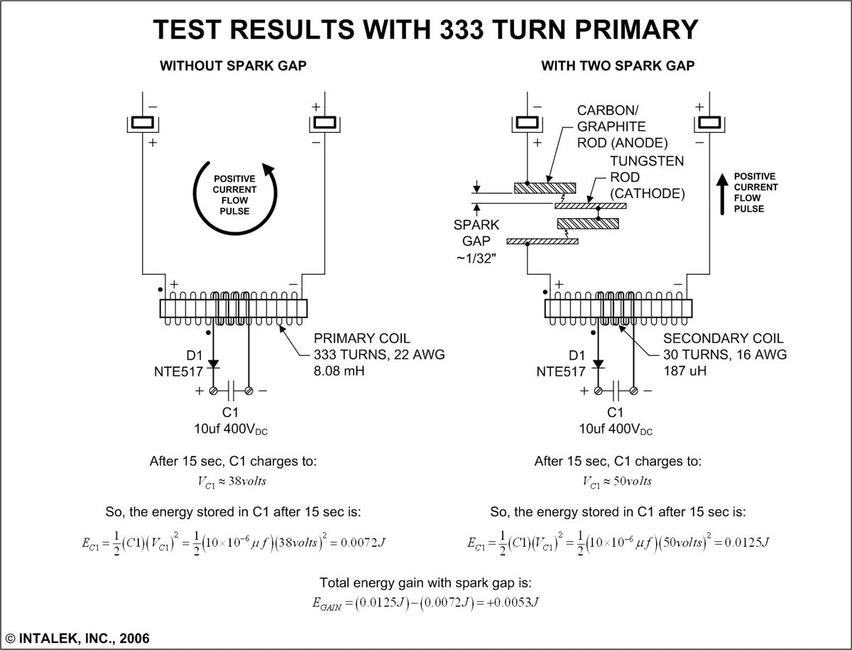
Figure 7. Test results using 333 turn primary and two spark gaps.

Figure 8. The COP calculation for 333 turn primary and two spark gaps.

Figure 9. Test results using 333 turn primary and one spark gap.

Figure 10. The COP calculation for 333 turn primary and one spark gap.

Figure 11. Wimshurst Generator test platform electrical schematic using 90 turn primary.
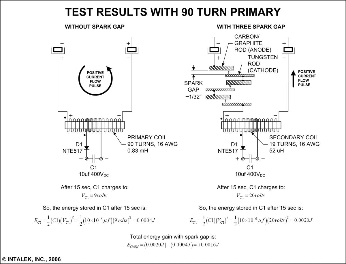
Figure 12. Test results using 90 turn primary and three spark gaps.

Figure 13. The COP calculation for 90 turn primary and three spark gaps.
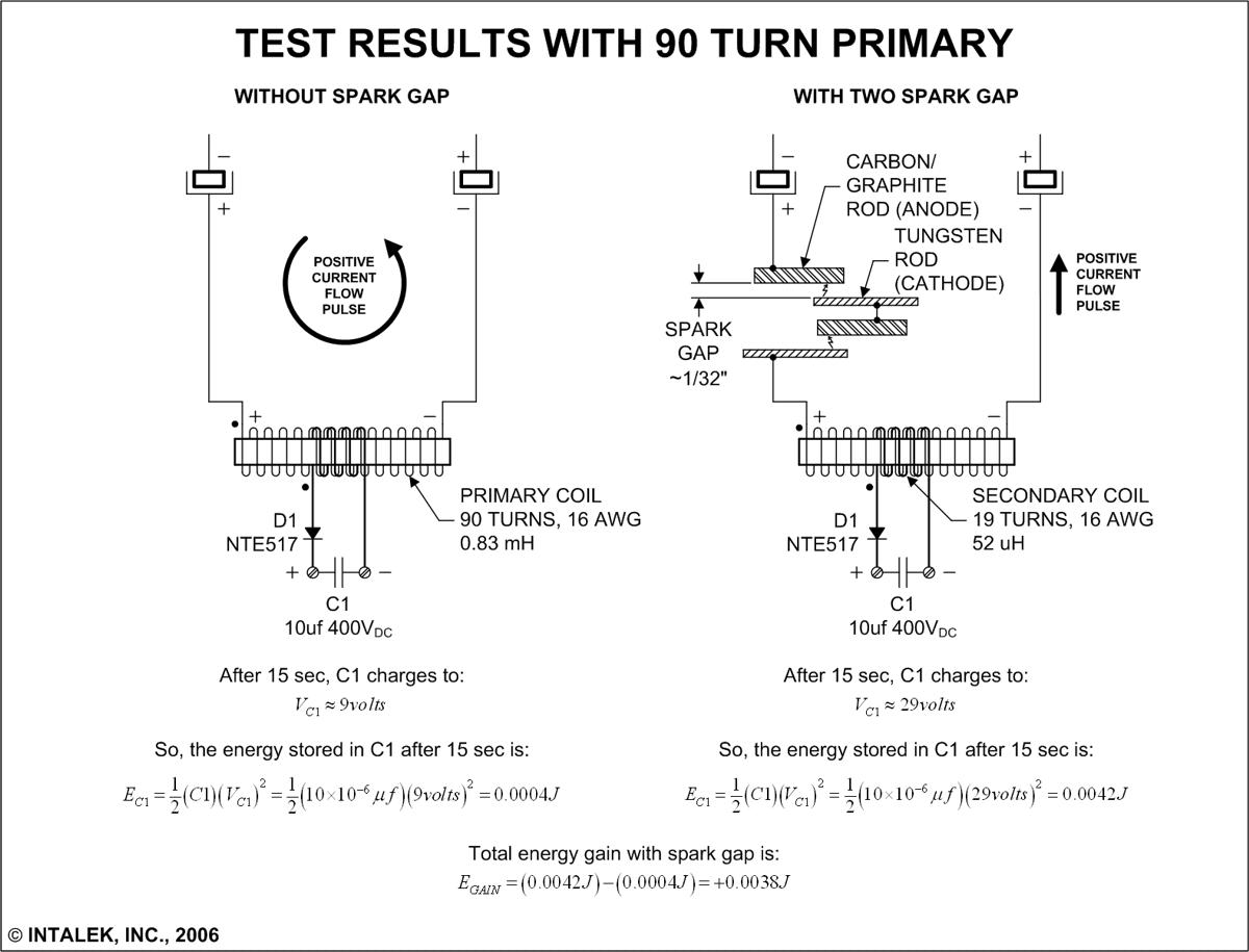
Figure 14. Test results using 90 turn primary and two spark gaps.

Figure 15. The COP calculation for 90 turn primary and two spark gaps.

Figure 16. Test results using 90 turn primary and one spark gap.

Figure 17. The COP calculation for 90 turn primary and one spark gap.

Figure 18. Wimshurst Generator test platform electrical schematic using 780 turn primary.

Figure 19. Wave trace across 780 turn primary with three spark gaps.
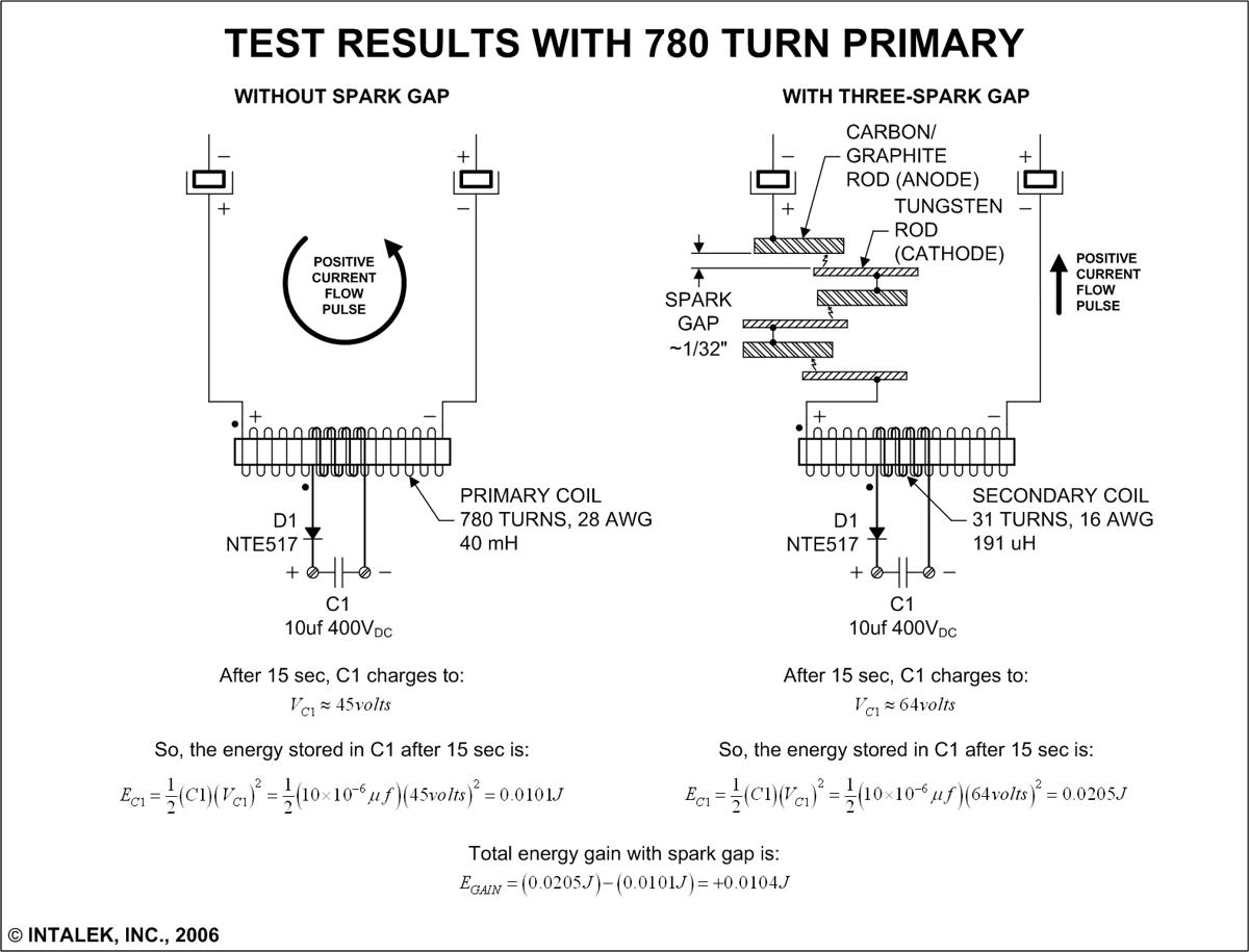
Figure 20. Test results using 780 turn primary and three spark gaps.
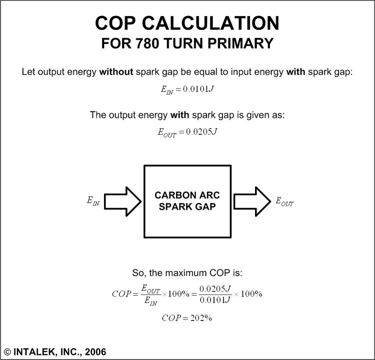
Figure 21. The COP calculation for 780 turn primary and three spark gaps.

Figure 22. Wave trace across 780 turn primary with two spark gaps.
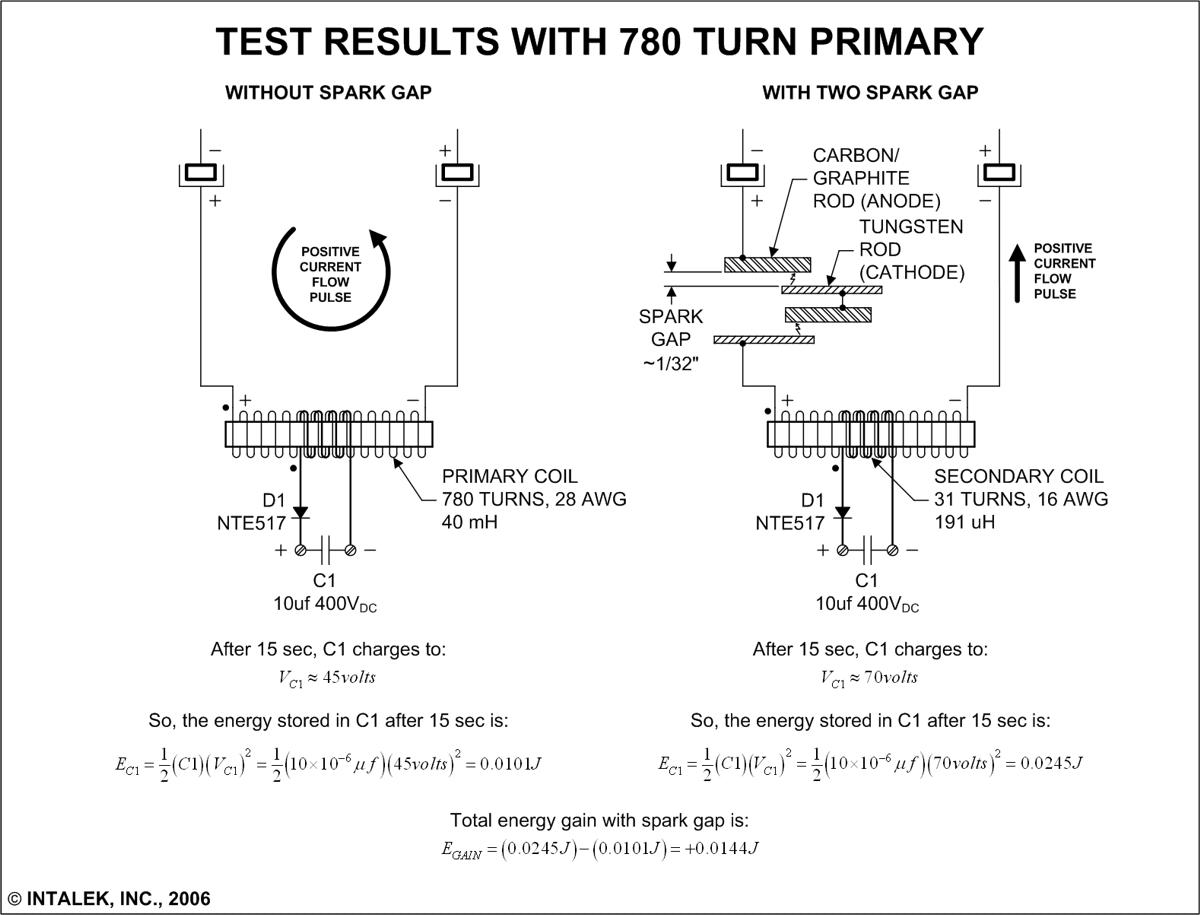
Figure 23. Test results using 780 turn primary and two spark gaps.
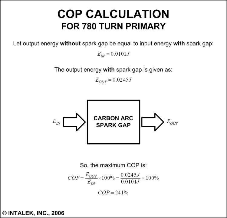
Figure 24. The COP calculation for 780 turn primary and two spark gaps.

Figure 25. Wave trace across 780 turn primary with one spark gap.

Figure 26. Test results using 780 turn primary and one spark gap.

Figure 27. The COP calculation for 780 turn primary and one spark gap.

Figure 28. Wave trace across 780 turn primary with no spark gaps.
My conclusion is the Carbon Arc is performing as a NEGATIVE resistance-like device in every test case. The bottom line is that there is MORE energy charging up capacitor C1 with the spark gap than without, and the greater the primary inductance, the greater the amount of energy that is collected. More energy is collected with two spark gaps than one due to constructive electromagnetic wave effects, and less energy is collected with three spark gaps than two due to destructive electromagnetic wave effects.
The Carbon Arc looks very promising as providing excess energy, once properly harnessed.
Go to Spark Gap Experiments page
MORE INFORMATION